Progressive Failure Analysis by GENOA ®
I would like to write about GENOA ®, the CAE software for composites material failure.
Below is the URL of GENOA® .
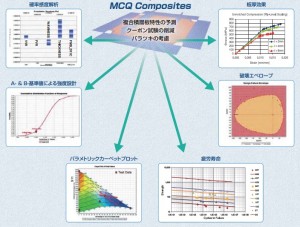
GENOA® is designed for PFA ( Progressive Failure Analysis ).
The failure simulation by the impact effect of pressure and explosion is available, and the fatigue failure simulation is also possible.
The impact failure analysis example can be seen in the URL below.
http://www.ad-tech.co.jp/products/genoamcq/function/genoa-impact
The story of " Space Shuttle Columbia Disaster " make GENOA® famous.
GENOA® revealed the accident cause that the forming material was attacked on the leading edge of the left wing, and this damage was the critical to lead to the disaster in the aerosphere. GENOA® succeeded to simulate the heating condition and failure propagation on the damaged edge during aerosphere enter.
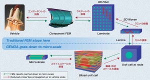
The composites material properties like the mechanical (static and fatigue) data, and the formation character are necessary as INPUT for GENOA®. The elements are set as micro-scale, and then they are scaled up to macro-scale. The elements data are formulated to 2D and 3D to simulate the actual configuration like the component parts. Below is the image of the steps.
( The image is referred from http://www.inter-lab.gr.jp/labsearch/wp-content/uploads/2014/09/ad-tech27_1.pdf )
GENOA® is good at simulating from the boundary condition between fiber and resin to the basic element including them, called as Multi Damage Tracking. The analysis after 2D configuration is conducted by the conventional FEM analysis.
The one of the features of GENOA® would be the consideration of the detail contents as initial condition like the defect during the manufacture, the residual stress by the curing shrinkage. The cracking propagation is simulated considering Mode I, II and mix mode damage system, based on the cracking density, fiber/interlaminar damage.
GENOA® consider the various stress mode like tensile, compression, shear and rotation. The rotation mode is not familiar with me, so I need to study more about it.
The summary of the rotation mode is like the ply to ply deformation as rotation, and it would be the one of the interlaminar shear mode.
The good example to understand GENOA® analysis is shown in the URL below.
http://www.ascgenoa.com/newsletter/18/index.jsp
You can see the simulation steps as below.
1. PFA strength/strain based evaluation to determine the crack path
2. Crack propagation analysis using DCZM/CCZM based on crack path predicted by PFA.
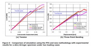
Actual test data comparison between DCZM/CCZM is shown as below.

( The image above is referred from http://www.ascgenoa.com/newsletter/18/index.jsp )
It would be the surprising result that the initial S-S line simulation showed good correlation in the low load area.
There still remains some error between simulation and test, but PFA simulation showed good matching.
Today I introduce the CAE software for composites materials.
It should be amazing that the simulation is very close to the reality.
But there exist also concerning.
"The increase of the engineers and researchers who believe the CAE result without any tests"
It is very dangerous status when I remind my career as the composites designer.
CAE technique is strongly affected by the skill of the operators.
I have the impression that some presenters explained their simulation results without any actual tests when I have attended the congresses.
I used CAE during the parts design too and I agree that it is very useful tool for the composite design process.
But I had the much higher weight on the actual test than CAE.
My basic concept is; CAE shall be modified to meet the correlation with the actual test. It should be impossible to assume 100% status by CAE. All of the engineers and researchers should understand the LIMIT of CAE and continue to modify CAE condition to make it match to the actual test. It shall be also necessary to prepare the safety net to avoid the accident chain.
I hope it helps.


